|
Being able to draw an object in CAD is one thing, but as I wanted to use plywood milled using CNC routing, I would need to go through a few more steps before I could give the CNC router operator CAD files he could use. The decision to use plywood milled by CNC routing has implications at every stage of the design. The fact that plywood is a sheet material means that I’ll have to break it down into parts that assemble together. It feels like I have to put my IKEA thinking cap on and work out a flat-pack arrangement of parts and the order they should be assembled. I need to become the cartoon man in the IKEA instructions. 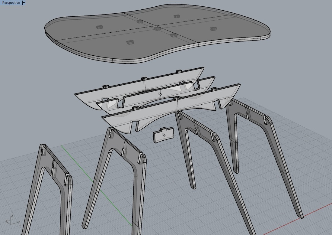 An example of how one of my pieces is broken down into parts which assemble together. CNC routers use a vacuum to hold down the sheet and pieces cut from the sheet. I was advised to space out the pieces to leave a ring of plywood around each piece, which helps stabilise the milling of each neighbouring piece. For standard cuts, it should be a minimum of 20 mm. For the edges which have been milled with a fillet bit with 16mm curvature radius, I was advised it should be at least 30 mm to avoid the bit from impacting neighbouring pieces. With the knowledge about the various bits that CNC routers have, and how the pieces milled by them should be spaced out on a sheet, the thing left to do is to mark on the CAD file which bit is to be used where. As mentioned in a previous post, a good thing to do at this stage would be to obtain the submission guidelines document from the CNC routing company outlining how they would like you to do this. There are three main types of cuts/milling you can indicate in a CAD file for CNC cutting: profile, pocket and engraving. Note I'm not talking about the kinds of router bits here - I'm specifically talking about the relationship between the path a router takes and the lines you draw in CAD. An engraving line in a CAD file shows the exact path that the centre of the bit should take. You would of course need to be aware of the thickness of any bit you want to use for engraving lines. A profile line doesn’t show the path that the bit should take, but the edge that should be the result of the cut. For example, if you wanted to cut out a square, you could draw the outside edge of this square as ‘profile’ lines. The actual centre line that the router would take would be offset a bit off this line, but that’s what the CNC router operator can work out. The converse is true for cutting out a cavity within a shape. Note that for internal corners, you need to do some extra thinking. Because router bits spin on a vertical axis, they can't do sharp corners. They will try to go in as far as possible but they will leave corners rounded with a radius equal to the radius of the bit being used. This might not matter in many cases. For example, the internal corner made by a chair leg and the underside of the seat base is fine to be curved. However, if you need to house a piece with sharp angled corners, then leaving the internal corners to be rounded/curved by the router bit won't do - the piece won't fit. For this case, you need to draw rounded corners yourself, basically instructing the router to venture enough into each corner to ensure the piece to be housed, with all its sharp edge, does indeed fit. 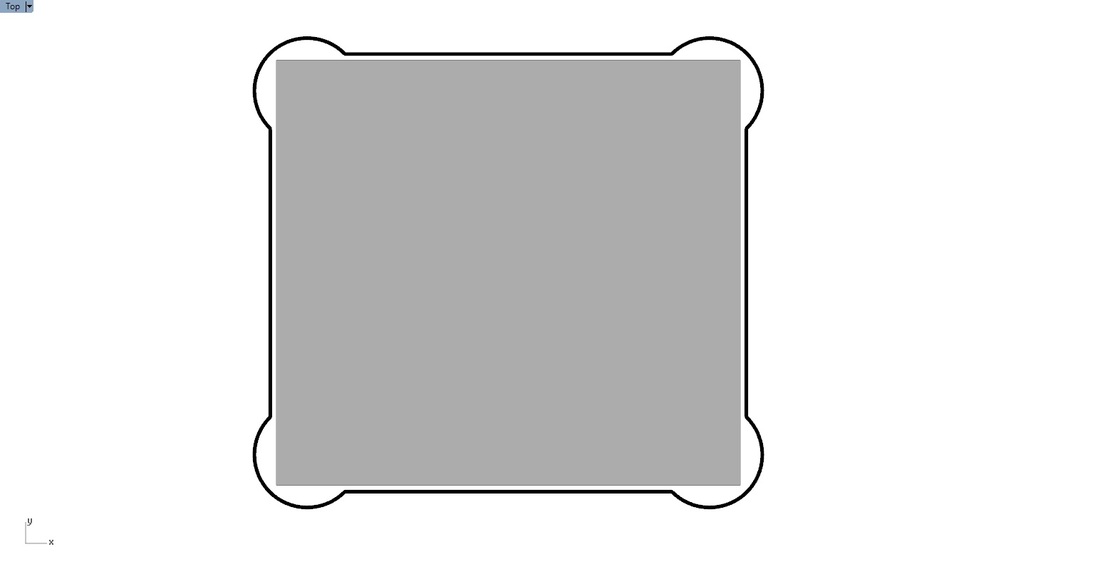 The black line is the profile line you should draw to ensure the grey piece will fit. A pocket line is the same as a profile line except it doesn’t go all the way through. It shows the boundaries of the pocket milled out of the sheet, to a specific depth. The inside corner considerations apply to this too. So putting this together, a CAD file for CNC routing should be a collection of lines grouped into layers, one layer for every combination of type of cut/mill and bit. Examples are:
Here's an example based on the submission guidelines document from Power To Make: 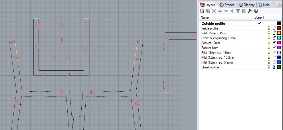 A CNC router operator can then program the router using that information. It’s then just a matter of picking up the cut pieces, assembling and finishing the product.
Comments
|
AuthorI'm Nicolaas, a software engineer with a creative streak. ArchivesCategories
All
|
 RSS Feed