|
If you are familiar with routers and electric drills as woodworking tools, then you can imagine a Computer Numerical Control (CNC) router as one of these attached to a robot arm. You can program this arm to cut a material (like plywood) along the lines you want by preparing a CAD file formatted in a certain way. But first, I'll explain a bit more about CNC routers based on what I've learned so far with the CNC routing company I use, and how I found this company in the first place. Here's a great video showing a CNC router in action, cutting someone's neat design for a snap-together bunk bed: A ‘bit’ is the technical term for the spinning metal item that actually cuts the plywood. As with drills and routers, there are various bits available for use in a CNC router:
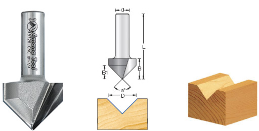 V-Bit. Sourced from www.toolstoday.com
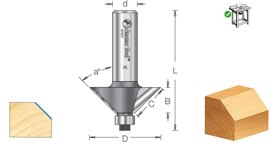 Chamfer bit. Sourced from www.toolstoday.com
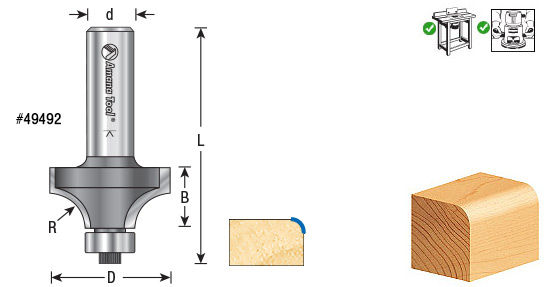 Fillet bit. Sourced from www.toolstoday.com
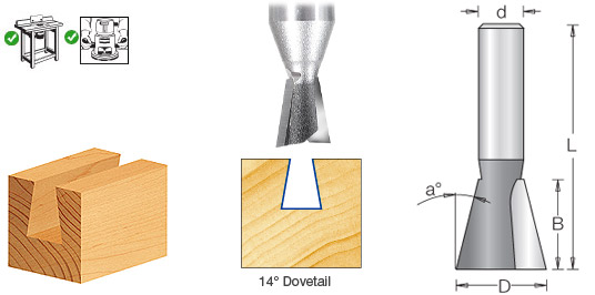 Dovetail bit. Sourced from www.toolstoday.com In essence, CNC routers can only mill one side of the sheet. There is a way to mill the other side, but it's one you should try after becoming familiar with the standard one-side-only process first. I'll go into that in a future post. Because CNC routers use spinning bits to mill, it is generally not possible to have precise square or angular internal corners. It’s like using a round sponge to clean a corner of a room - you won’t be able to reach right into the corner. If you wanted to fit a square piece into an internal corner of a CNC-cut piece, then you’d need to cut further into the corner, as shown in the diagram: 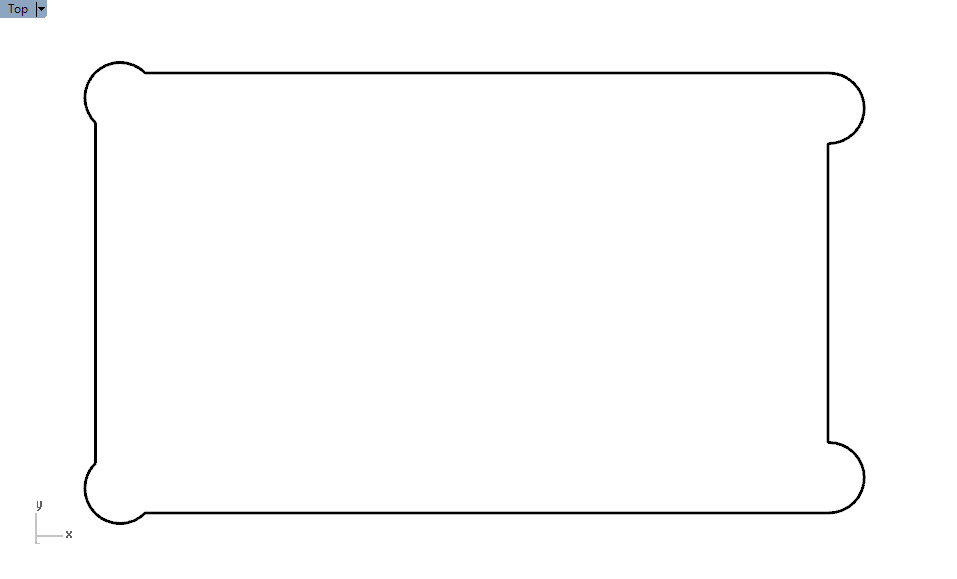 These corners are known as ‘dogbone’ corners, and I might more about them in a future post.
The accuracy you can achieve with CNC routing is quite impressive. It is normally accurate down to 0.1 mm. Yes, a tenth of a millimetre. When I’m drawing in CAD (I’ll write about CAD in my next post) I end up having to make decisions such as: “do I want this slot to be 9.2 or 9.3 mm wide?”. This accuracy is one of the reasons why I enjoy using CNC routing so much; the shape I draw in CAD will look exactly like its real life counterpart. When I was trying to find a company offering CNC routing services, I really had to ring around. Some companies only have a half-size machine or cater for specialised 3D milling or large-scale fabrication of kitchen doors, etc. I found that most companies are not geared towards people just submitting CAD files for them to use in milling a specified material. My guess is that they don't want to spend the time educating potential customers in how to properly format CAD files for them to use - they'd rather see it as a custom design job than a pure CNC cutting service. However, I found a great company in Melbourne called Power To Make, and have used them for all of my CNC routing so far. They have created a useful submission guidelines document and have even bought new dovetail bits for me when theirs broke to the sheer amount of dovetail groves I drew in my CAD files.
Comments
|
AuthorI'm Nicolaas, a software engineer with a creative streak. ArchivesCategories
All
|
 RSS Feed